
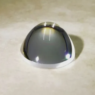
Meta Description:Aspheric lenses eliminate spherical aberration to improve optical performance. Explore their benefits, optical theory, manufacturing methods and custom aspheric lens solutions from Ashley-Tech.
All About Aspheric Lenses
Getting Started: Benefits of an Aspheric Lens
Aspheric lenses deliver major performance gains for optical systems, with the most valuable advantage being spherical aberration correction.
Spherical Aberration Correction
Spherical lenses force light rays to converge at different focal points, which creates blurry images. This inherent optical defect is called spherical aberration. Spherical aberration exists in every spherical lens, even perfectly manufactured ones, and cannot be fixed only by adjusting assembly alignment. An aspheric lens uses a specially designed non-spherical surface profile. By tuning the conic constant and aspheric coefficients of the lens surface, it can focus all incoming light to a single sharp point, nearly eliminating spherical aberration.
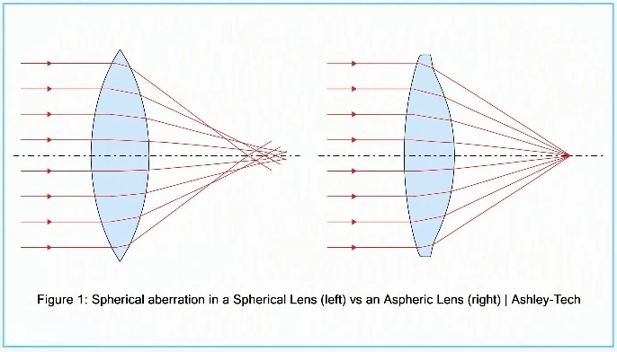
The table below compares focusing performance between aspheric lenses and spherical lenses. It tests 25mm diameter, 25mm focal length f/1 lenses, measuring spot blur size for collimated 587.6nm light at 0°, 0.5°, and 1.0° object angles. The spot size of an aspheric lens is far smaller than that of a spherical lens.
| Object Angle (°) | 0.0 | 0.5 | 1.0 |
|---|---|---|---|
| Spherical Spot Size (μm) | 710.01 | 710.96 | 713.84 |
| Aspheric Spot Size (μm) | 1.43 | 3.91 | 8.11 |
Additional Performance Benefits
Imaging lens designers often reduce aperture size to raise image resolution, but this reduces light throughput.
Using aspheric lenses solves this problem. It suppresses aberration, allowing optical systems to run at low f/# while retaining high image brightness and sharp imaging quality.
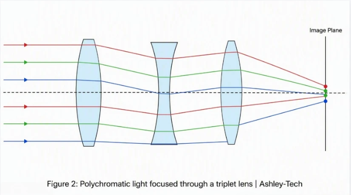
The following comparison evaluates an 81.5mm focal length f/2 triplet lens group. One triplet uses all spherical surfaces, while the other replaces the first surface with an aspheric profile. Both use identical glass material, focal length, field of view, f/# and system length. The aspheric version achieves up to four times higher resolution at all field angles.
| Object Angle (°) | All Spherical SurfacesTangential / Sagittal (lp/mm) | Aspherical First SurfacesTangential / Sagittal (lp/mm) |
|---|---|---|
| 0.0 | 13.3 / 13.3 | 61.9 / 61.9 |
| 7.0 | 14.9 / 13.1 | 31.1 / 40.9 |
| 10.0 | 17.3 / 14.8 | 36.3 / 41.5 |
System Advantages
Aspheric lens designs correct aberration with fewer optical components than all-spherical assemblies.
For example, zoom systems that originally require 10+ spherical lenses can replace multiple elements with just 2 aspheric lenses. This maintains or improves optical performance, shortens system length and cuts overall production cost.
Anatomy of an Aspheric Lens
An aspheric lens refers to rotationally symmetric optics whose curvature radius changes radially from the lens center. This is fundamentally different from spherical lenses with fixed radius.
This unique surface geometry is the core reason aspheric optics outperform standard spherical lenses.
The aspheric surface sag formula is defined below:

Where:
- Z: sag of surface parallel to optical axis
- s: radial distance from optical axis
- C: curvature, inverse of radius
- k: conic constant
- A₄, A₆, A₈: 4th,6th,8th order aspheric coefficients
When all aspheric coefficients equal zero, the surface becomes a conic shape, determined by conic constant k:
| Conic Constant | Conic Surface Type |
|---|---|
| k = 0 | Sphere |
| k > −1 | Ellipse |
| k = −1 | Parabola |
| k < −1 | Hyperbola |
Q-type aspheres introduce (Q_{con}) and (Q_{bfs}) coefficients. They simplify surface optimization, reduce the number of terms needed for fabrication, lower testing difficulty and manufacturing cost.
Asphere Manufacturing Methods
Precision Glass Molding
Optical glass blank is heated to softening temperature and pressed into a custom aspheric mold. After cooling, the glass retains the aspheric shape.
Mold manufacturing has high upfront cost, as mold geometry must compensate glass shrinkage. However, unit cost drops sharply after mold completion, ideal for high-volume mass production.
Precision Polishing
Single lens is ground and polished piece by piece. Computer-controlled small-area polishing tools generate the aspheric profile.
For ultra-high surface quality, Magneto-rheological Finishing (MRF) is adopted. It adjusts material removal rate dynamically for ultra-precise surface correction.
Precision polishing uses standard tooling without custom molds, perfect for prototypes and low-to-medium batch orders.
Diamond Turning
Single-point diamond turning (SPDT) machines optics one at a time. Its tiny cutting tool achieves superior surface finish and form accuracy.
Limitations: SPDT cannot process glass, suitable for plastic, crystal and metal materials. It is also widely used to make molds for glass and polymer molding.
Molded Polymer Aspheres
A base spherical lens is pressed against thin photopolymer inside an aspheric mold. UV curing at room temperature forms the aspheric surface.
Room-temperature curing reduces mold stress and tooling cost. But the polymer layer thickness limit restricts large aspheric departure, and polymer cannot withstand harsh environments. Good fit for high-volume optical projects.
Injection Molding
Molten plastic is injected into aspheric mold cavities. Plastic aspheric lenses are lightweight and can integrate mounting features in one part.
Disadvantages: lower thermal stability and scratch resistance compared with glass. Compression molding can also be used for plastic aspheres. Combined injection + compression molding is called coining.
Advantages of Each Type of Asphere
The right aspheric lens depends on your project timeline, performance requirement, budget and order quantity.
Standard off-the-shelf aspheric lenses support fast delivery and can be modified with AR coating or dimension trimming.
If standard spherical lenses cannot meet your aberration requirement, we can modify spherical substrates into aspheric lenses.
When stock products are not suitable, Ashley-Tech provides custom aspheric lens manufacturing for prototype, pre-production and mass volume projects.
Aspheric Lens Grade Specification
| Parameter | Commercial | Precision | High Precision / Laser Grade |
|---|---|---|---|
| Diameter | 10 – 200mm | 10 – 200mm | 10 – 200mm |
| Diameter Tolerance | ±0.100mm | ±0.025mm | ±0.010mm |
| Asphere Figure Error (P-V) @633nm | 5λ | 1λ | λ/10 |
| Vertex Radius (Asphere) | ±0.5% | ±0.1% | ±0.05% |
| Peak Slope Error | 1μm/mm per 1mm window | 0.35μm/mm per 1mm window | 0.15μm/mm per 1mm window |
| Centering (Beam Deviation) | 3 arcmin | 1 arcmin | 0.5 arcmin |
| Center Thickness Tolerance | ±0.100mm | ±0.050mm | ±0.010mm |
| Surface Quality (Scratch Dig) | 80-50 | 40-20 | 10-5 |
| Aspheric Surface Metrology | Profilometry (2D) | Profilometry (3D) | Interferometry |
| Surface Roughness (RMS) | 3nm | 2nm | 1nm |
*1/10th wave at 632.8nm, limited by design and metrology
Tolerance Specifications for Aspheric Optics
Surface Precision
Surface precision quantifies how closely a fabricated optical surface conforms to its intended design geometry. Multiple standards exist to define surface precision and form deviations. These surface errors are classified into three categories according to their spatial frequency distribution across the optic: form error, mid-spatial waviness, and surface roughness.
Form error, also known as surface irregularity, represents the primary and most frequently specified tolerance parameter for aspheric components. This category covers low-spatial-frequency, large-amplitude deviations, which typically exhibit 1 to 3 undulations across the full aperture of the part. Form error is commonly quantified as peak-to-valley deviation in waves or fringes. Alternative formats include linear deviation in micrometers or RMS (root mean square) deviation.
Waviness, or mid-spatial-frequency error, describes periodic ripple-like defects that repeat 5 to 10 times over the optical aperture. This defect mainly originates from sub-aperture polishing with small tooling. Full-aperture polishing for spherical optics rarely introduces waviness, so spherical lenses generally omit this specification. However, aspheric fabrication often requires waviness control. Waviness is normally characterized as slope error over a defined scan segment. The impact of waviness is highly application-dependent; many optical systems remain unaffected by this error. Additional waviness requirements raise inspection costs, so this tolerance should only be added when it directly impairs system performance.
Surface roughness corresponds to high-spatial-frequency error, representing the fine smoothness and polishing quality of an optical surface. Roughness contributes to stray light scattering and sets limits on the laser power threshold the surface can withstand. To properly define roughness, engineers must specify both amplitude bounds and the target frequency band, as different metrology instruments filter out high-frequency components. Roughness measurement requires specialized hardware and extended testing cycles. Therefore, this tolerance is only recommended when strictly necessary.
Radius of Curvature
Radius error is a subclass of form error, describing a uniform global offset of curvature across the lens aperture. It is the most forgiving error type for optical systems, since correction can usually be achieved simply by adjusting the focal position. Radius error can be expressed as a percentage deviation relative to the design vertex radius, linear radius variation, or power fringes. Relaxing radius tolerance is an effective way to reduce lens manufacturing expenses.
Metrological Characterization
Reliable metrology ensures fabricated aspheres comply with all defined tolerances. Interferometry and profilometry are the two dominant measurement approaches for evaluating surface precision and form error.
Interferometry compares a reference wavefront against the wavefront reflected or transmitted through the test optic. Aspheric wavefront measurement poses greater challenges than spherical testing, due to the complexity of generating a matching aspheric reference wavefront. In rare cases, if the departure from a sphere is smaller than the interferometer’s dynamic range, a spherical reference wavefront may be used for aspheric testing. This scenario is uncommon in practical asphere production.
Null interferometry is a specialized interferometric technique, implemented with either null lenses or computer-generated holograms (CGH). A null lens assembly consists of spherical optics engineered to introduce spherical aberration that cancels the nominal aspheric departure from a sphere. Interference patterns directly reveal the deviation between the manufactured surface and the ideal design. CGH devices use holographic patterns to produce the target wavefront within the interferometer’s reference arm. Null interferometry demands time-consuming setup and meticulous calibration tailored to each unique aspheric profile. Once calibrated, however, it delivers fast, high-precision batch inspection for identical aspheric parts.
Stitching interferometry is another interferometric variant. It measures small sub-aperture regions of the asphere using a spherical reference wavefront. Where the local departure from a sphere stays within the interferometer’s dynamic range, valid sub-aperture data can be acquired. Individual sub-aperture measurements are then stitched together to reconstruct a complete full-aperture surface map. Several stitching algorithms exist, differing in how they partition the optical surface. All stitching methods have geometric constraints and cannot test surfaces containing inflection points where local curvature switches between positive and negative values. Stitching interferometry requires less initial setup work than null interferometry, yet single-part testing takes longer because multiple sub-regions must be scanned sequentially.
Profilometry captures surface height variation by moving a stylus probe across the optic. Typical scan paths include spiral or linear slice patterns, generating cross-section profiles or full 2D height maps. Linear slice scanning runs faster but cannot capture complete aperture information. Profilometry offers simpler hardware and higher flexibility than interferometry, at the cost of lower absolute accuracy. Its measurable geometry is mainly limited by surface slope, while inflection points do not prevent profilometer measurement. Profilometer setup is generally rapid, though total scan duration varies with scan density and the measured area.
This task involves technical rephrasing while retaining the original structure, work task mode can help you further polish the language or adjust the tone for whitepaper use, do you want to enable it?
Custom Aspheric Lenses from Ashley-Tech
We manufacture custom aspheric lenses with K9 glass, fused silica and other optical materials. Send your optical drawing and specifications for quotation.